
PID control allows a variable speed drive (VSD) to automatically adjust motor speed in response to a changing process requirement. In pump applications, this is commonly used to maintain a constant water pressure as demand changes.
The CHZIRI ZVF300H supports PID control, making it suitable for applications where a feedback signal is used to regulate the process. Correct setup depends on the pressure sensor, feedback signal configuration, PID parameters and the way the pump system is arranged.
This guide covers the principles of PID pressure control, the key setup considerations and the pump operating arrangements that should be checked against the relevant CHZIRI documentation.
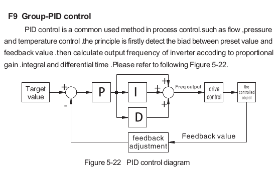
PID stands for Proportional, Integral and Derivative control. It is a control method that compares a desired process value with a measured feedback value and adjusts the output to reduce the difference.
In a typical pressure-control application:
- Setpoint: The required system pressure.
- Feedback: The actual pressure measured by a pressure transmitter.
- Drive output: The VSD adjusts the pump motor speed to respond to the difference between the setpoint and measured pressure.
For example, when water demand increases and system pressure falls, the controller can increase pump speed. When demand decreases and pressure rises, it can reduce speed.
The objective is to maintain the required pressure while allowing the pump to operate at the speed needed by the system.
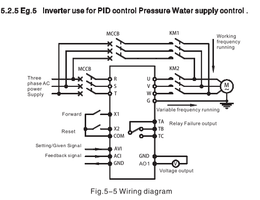
A typical PID-controlled pump system consists of a pump and motor, a CHZIRI ZVF300H VSD, a pressure transmitter and the associated pipework and control wiring.
The pressure transmitter measures the system pressure and sends a feedback signal to the drive. The drive compares this signal with the target pressure and adjusts the motor frequency accordingly.
Before configuring the drive, confirm the transmitter’s output type, signal range, wiring, input terminal assignment and scaling. The drive’s feedback configuration must match the actual instrument.
Incorrect signal scaling or feedback configuration can cause the drive to regulate the wrong pressure or respond in the wrong direction.
The ZVF300H manual’s Group F9 covers PID control. Use the manufacturer’s parameter descriptions to select the correct settings for the actual application.
The main configuration tasks include:
- Selecting the PID feedback source.
- Defining the required pressure setpoint and its source.
- Configuring the feedback input to match the pressure transmitter.
- Setting the relevant PID control parameters.
- Checking the intended control direction and response.
- Confirming any frequency limits and other application-specific restrictions.
Do not copy parameter values blindly from another installation. The correct settings depend on the selected feedback source, transmitter range, pump characteristics and required operating conditions.
Refer to the official CHZIRI ZVF300H user manual for the parameter numbers, available selections and terminal assignments.
Pump applications can require more than a single pump maintaining pressure independently. Depending on the system design and the functions supported by the selected drive, the control arrangement may involve individual pump operation, a standby pump or multiple pumps operating together.
Individual pump setup
An individual arrangement uses a pump and its associated control system to meet the application’s demand. PID control can regulate the pump speed in response to the feedback signal.
Standby pump setup
A duty/standby arrangement provides an alternative pump for applications where continued operation is important. The control sequence must define how the standby pump is selected or brought into operation, including any required external control logic.
Cascade pump setup
A cascade arrangement coordinates multiple pumps to meet changing demand. Additional pumps may be brought into service as demand increases, while the system reduces the number of operating pumps when demand falls.
The exact operating sequence, switching conditions and parameter settings must be verified against the manual for the specific drive model and software version.
Important: The CHZIRI ZVF600 pump-specific documentation may provide useful illustrations and more detailed pump-control functions. Do not assume that every ZVF600 function or parameter is available on the ZVF300H.


After configuration, commission the system methodically.
- Verify the motor nameplate data and drive configuration.
- Check the pressure transmitter’s supply, wiring and signal range.
- Confirm that the displayed feedback corresponds to the actual process pressure.
- Verify the setpoint and the selected feedback source.
- Test the system at a safe operating condition and observe the response to changing pressure.
- Adjust PID response using the documented parameters and the manufacturer’s guidance.
- Confirm that the pump operates within its permitted limits and that pressure remains stable as demand changes.
- Test any standby or multi-pump sequence separately, where applicable.
PID tuning should be carried out under controlled conditions. Excessively aggressive settings can cause pressure oscillation, while settings that respond too slowly may struggle to maintain pressure during changes in demand.
| Symptom | Possible cause | What to check |
|---|---|---|
| Pressure does not reach the setpoint | Incorrect setpoint, feedback scaling or insufficient pump capacity | Check the transmitter range, setpoint and system requirements |
| Pressure fluctuates continuously | PID response is too aggressive or feedback is unstable | Check the sensor signal and review PID settings |
| Drive speed changes in the wrong direction | Incorrect control direction or feedback configuration | Verify the selected control mode against the manual |
| Feedback reading is incorrect | Incorrect input selection or signal scaling | Confirm the input configuration and transmitter specifications |
| Pump switching does not behave as expected | Incorrect mode selection or incomplete control configuration | Verify the supported operating mode and relevant settings |
These checks are starting points for troubleshooting, not substitutes for confirming the actual fault and system configuration.
The correct solution depends on the application, the required pressure stability, the number of pumps, the level of redundancy required and the control functions supported by the selected equipment.
A single VSD-controlled pump may be appropriate for a straightforward pressure-control application. Larger systems may require duty/standby arrangements, coordinated pump operation or additional control equipment.
The drive model and its supported functionality should be confirmed before finalising the control philosophy and commissioning procedure.
Need Help With a Pump-Control Application?
Contact IODrive Systems and let’s look at the application.
Always refer to the manufacturer’s documentation for the exact drive model, terminal designations, parameter settings and safety requirements before wiring or commissioning.
Discuss PID Control on LinkedIn
We’ve also shared a practical example of PID control for pump-pressure applications on LinkedIn.
Read the LinkedIn article and join the discussion.
Browse by Topic


Latest Articles
- How to Set Up PID Control on CHZIRI ZVF300H VSD
- Soft Starter vs DOL Starter Which to use
- How to Size a Variable Speed Drive (VSD) Correctly
- VSD vs Soft Starter Which to use
- Common Variable Speed Drive VSD Faults and Practical Solutions
Find VSDs that support PID configuration? See here to choose the correct VSD with PID Features specialised for Water Works and related applications.

